使用宽带电压和电流反馈运算放大器时的应用基础
(Click to Enlarge Image)
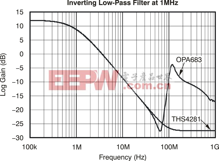
Figure 11. Simulated inverting low pass filter design.
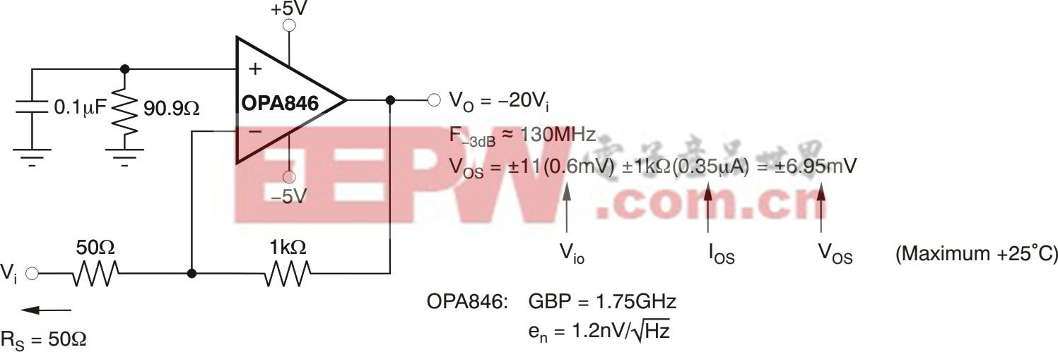
D. Wideband DC-coupled amplifiers with good DC precision. VFB op amps have better input offset voltage and (for bipolar amplifiers) matched input-bias currents. As a result, considerably lower output DC-offset voltage and drift can be delivered as compared to equivalent CFB implementations. This consideration becomes more important as the required gain increases.Figure 12shows an example high gain, DC-coupled inverting amplifier stage using a non-unity gain stable VFB. The OPA846 offers very good input offset voltage and offset current along with a low 1.2 nV/√Hz input voltage noise.
To take advantage of this low noise, the gain of -20 circuit in Figure 12 implements a matched 50 Ω input impedance using only the input resistor and then a 1 kΩ feedback resistor. If a 50 Ω DC-coupled source impedance is assumed, the required bias current cancellation resistor on the non-inverting input would be 100 Ω| in parallel with 1 kΩ = 90.9 Ω. Decouple this resistor with a parallel capacitor to reduce its high-frequency noise contribution.
Another interesting aspect of this circuit is the noise gain (NG), which is also the gain for the input offset voltage, is reduced below the inverting signal gain because of the 50 Ω source resistor. Including that value in the NG equation gives an NG = 11 while the signal gain will be -20.
(Click to Enlarge Image)
Figure 12. Inverting gain of -20, low-output Vosdesign, using the OPA846.
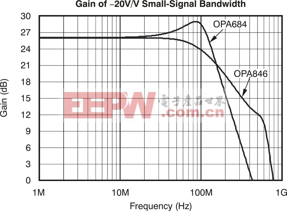
This high-gain inverting implementation using the OPA846 can also be done using a low-power current feedback amplifier. For comparison, an OPA684 low-power CFB is compared inFigure 13for the simulated frequency response. Since high equivalent gain bandwidth is a natural advantage for CFB amplifiers, the OPA684 gives very similar small signal bandwidth to the OPA846 of approximately 150 MHz. The OPA684 uses 1.8 mA quiescent current while the OPA846 uses 12.9 mA.
(Click to Enlarge Image)
Figure 13. Gain of -20V/V simulated performance using VFB and CFB devices.

加入微信
获取电子行业最新资讯
搜索微信公众号:EEPW
或用微信扫描左侧二维码