Locked-sync sine generator cov
Abstract: This circuit synchronizes a sinewave output through three decades of frequency (20Hz to 20kHz) while maintaining low THD and constant amplitude.
A similar version of this article appeared in the September 18, 2009 issue of EDN magazine.Analog applications such as testing, calibration, and general system operation often require a sine waveform of accurate amplitude and frequency, with low total harmonic distortion (THD). Some applications demand that the generator of such waveforms have the ability to accurately synchronize the output with an external timing signal. Simple sinewave generators can offer various degrees of this performance, but maintaining low THD with constant amplitude is a problem, particularly if the output and the synchronization signal must remain locked through an extended range of frequencies.The circuit of Figure 1 can synchronize a sinewave output through three decades of frequency (20Hz to 20kHz) while maintaining low THD and constant amplitude (Table 1). The synchronizer IC (74HC4046) is a phase-locked loop (PLL) complete with VCO and phase/frequency detector. It has three internal phase detectors, but the one used here (number 2) has a frequency-capture range equal to that of the VCO frequency range (fMAX - fMIN).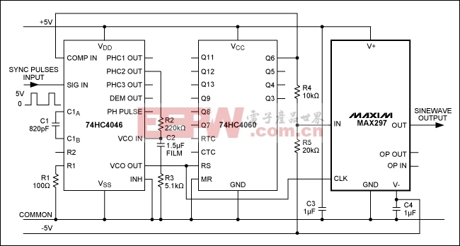 A switched-capacitor lowpass filter (MAX297), whose cut-off frequency (by design) equals 1/50th of the clock frequency applied to it, has for signal input the same square wave used for the PLL feedback, and its clock input is attached to the VCO output. Because the clock and signal inputs always have a frequency ratio of 64, the input signal always falls within the filter bandpass. No input harmonics fall within this bandpass, because the ratio of FCLOCK to frequency is 50 for all of them. (For the lowest-possible (second) harmonic, the ratio is 32.)The fact that the filter's input signal is a square wave (with 50% duty cycle) helps this application, because a square wave contains only odd harmonics of the fundamental, and the lowest-frequency harmonic is the third, which is well within the filter's deep-attenuation range. Output amplitude and distortion over the frequency range are shown in Table 1.You can frequency-modulate the synchronization signal, but that entails a compromise between the synchronization tracking speed (or maximum modulation frequency and depth) and the frequency locking range, which is set by the PLL's lowpass filter components (R2, R3, and C2). Modulation speed is limited for the values shown, because those values are optimized for an extended-frequency locking range. More information, including a full data sheet for the MAX297, are available for download.Table 1. THD and Amplitude vs. frequency, for Figure 1 circuit
| Frequency (Hz) | THD (%) | Amplitude (VRMS) |
| 20 | 2.775 | 1.470 |
| 50 | 2.650 | 1.472 |
| 100 | 2.525 | 1.472 |
| 200 | 2.250 | 1.473 |
| 500 | 1.002 | 1.473 |
| 1000 | 0.186 | 1.473 |
| 2000 | 0.260 | 1.472 |
| 5000 | 0.330 | 1.473 |
| 10000 | 0.405 | 1.473 |
| 20000 | 0.022 | 1.472 |
关键词: 电子电路图,generator

加入微信
获取电子行业最新资讯
搜索微信公众号:EEPW
或用微信扫描左侧二维码