6瓦FM功率放大器电路(英文)
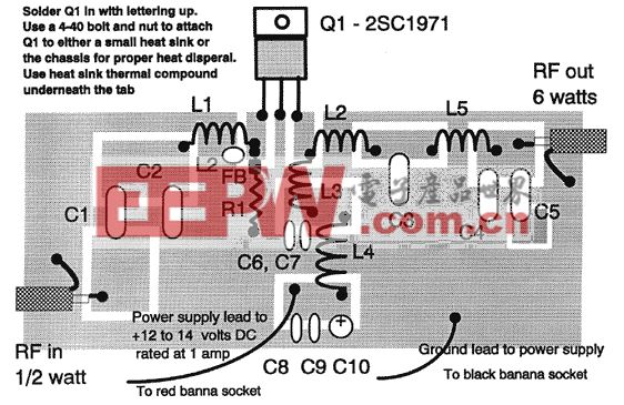
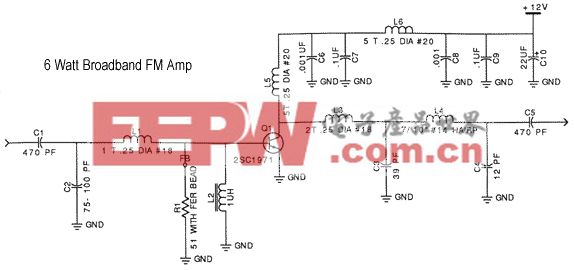
Assemble by soldering the components to the pads indicated. Keep coil, resistor, and capacitor leads as short as possible. The coils should be 3/16" to 1/4" above the board and separate turns by one wire diameter. Bend leads to form a little mounting foot for soldering to the circuit board. Tuning and power output are affected by the distance between the coil turns, you can make fine adjustments by either spreading or compressing the coil slightly. The area surrounding the pads is ground. C2, C3, C4, C6, C7, C8, C9, C10, L2, and R1 are soldered at one end to ground as well as the shield braid on the coax cables. Bolt Q1 to a small heat sink or the chassis with heat sink thermal compound or gray thermal pad underneath the tab. With an input level of 200-500mw, you should see an output of 5-6 watts. Be sure to have a proper dummy load (50 ohms) or tuned antenna connected to the output, doing otherwise will likely destroy the transistor.
Parts List
QuantityDescriptionPart Number(s)2470 pF mica capacitorC1, C5175 pF mica capacitorC2139 pF mica capacitorC3112 pF mica capacitorC420.001 uF disc or monolythic capacitor (marked either 102, .001, or 1n)C6, C820.1 uF disc or monolythic capacitor (marked either 104, .1, or 100n)C7, C9110 to 22 uF electrolytic capacitor (observe correct polarity)C1011 turn #18 tinned copper, 1/4" dia.L111 uH inductor, blue lumpy itemL212 turns #18, 1/4" dia.L317/10" #14, hairpinL425 turns #20, 1/4" dia.L5, L6156 ohm resistor with ferrite bead over lead at the base of end of Q1R112SC1971 RF transistorQ12SO239 socket2banana plug (1 each red and black)2banana socket (1 each red and black)1ferrite bead44-40 nuts44-40 boltsRG174 coaxial cablehookup wiresoldering lugs

加入微信
获取电子行业最新资讯
搜索微信公众号:EEPW
或用微信扫描左侧二维码