FM Transmitter Circuit
FM Transmitter Circuit
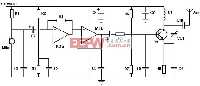
Parts List:
R1 4K7 R4 150K R7 3K9 (2K7)R2 4K7 R5 220R R8 120R (82R)R3 4K7 R6 4K7All resistors except R8 are at least 0.25W rated. R8 is at least 0.5W rated(the 0.6W metal film M-series from Maplin can be used for R1-R8).C1 1n C4 22uF C7 10n C10 1nC2 4u7 C5 1n C8 1nC3 1n C6 10n C9 33pFVC1 5-60pF IC1 LM358 Q1 ZTX108
Notes:
L1 is 0.112uH (this tunes to the middle of the FM band, 98 MHz, with VC1 at its centre value of 33pF). L1 is 5 turns of 22 swg enamelled copper wire close-wound on a 5mm (3/16") diameter former. Alternatively, you can have a fixed 33pF cap instead of VC1 and have L1 as an adjustable molded coil (eg UF64U from Maplin). VC1 will give you a tuning range of 85 - 125 MHz, and a possible choice is the Philips type polypropylene film trimmer (Maplin code WL72P). Two sets of oscillator bias resistors are given, the ones in the brackets give about 20% more RF power. Mike is our favourite Omnidirectional sub-mini electret (Maplin code FS43W). Ant is a (lambda / 4) whip monopole (eg 76 cms of 22 swg copper wire). Q1 is configured as a Clapp oscillator. Frequency modulation results from the audio voltage changing the transistor's base-emitter capacitance.
关键词: Transmitter Circuit

加入微信
获取电子行业最新资讯
搜索微信公众号:EEPW
或用微信扫描左侧二维码