使用非门电路制作的调频话筒(英文)-----FM Transmitter Using Logic Gates
作者:dolphin
时间:2012-11-22
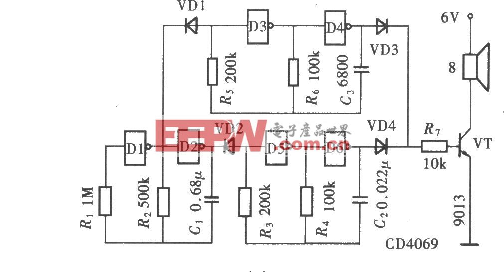
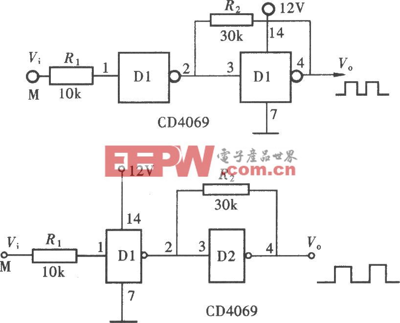
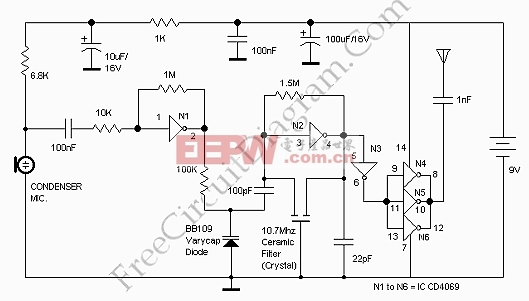
This is a FM Transmitter circuit. This circuit uses logic gates. This transmitter circuit has a RF oscillator. This oscillator uses 10.7Mhz ceramic filter and inverter N2 to drive the parallel combination of N4 to N6 through N3. Here is the circuit:
The output impedance will be low because these inverters are in parallel, so an aerial of 1/4h wavelength can be driven directly. There would be a lot of harmonics in the output of N4-N6 because the output of N4 to N6 is square wave. The 9th harmonics of 10.7Mhz (96.3Mhz) will hence be at the center of the FM band. As an audio amplifier, this circuit uses N1. It will amplify audio signals from the microphone and fed it to varycap diode. The capacitance of the varycap is varied by the signal that will vary the oscillator frequency that produce Frequency Modulation.

加入微信
获取电子行业最新资讯
搜索微信公众号:EEPW
或用微信扫描左侧二维码