ADL5535以及ADL5536应用电路
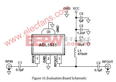
ADL5535应用电路 (评估板参考电路)


Figure 10 shows the schematic for the ADL5535 evaluation board. The board is powered by a single 5 V supply. The components used on the board are listed in Table 4. Power can be applied to the board through clip-on leads (VCC and GND).
Table 4. Evaluation Board Configuration Options
Component Description
Default Value
C1, C2 AC-coupling capacitors 0.1 μF, 0402
L1 DC bias inductor 470 nH, 0603 (Coilcraft 0603LS-NX or equivalent)
VCC and GND Clip-on terminals for power supply
C4, C5, C6 Power supply decoupling capacitors
C4 = 68 pF, 0603; C5 = 1.2 nF, 0603; C6 = 1 μF, 1206
ADL5536应用电路 (20 MHz to 1.0 GHz IF Gain Block)

Figure 10 shows the schematic for the ADL5536 evaluation board. The board is powered by a single 5 V supply. The components used on the board are listed in Table 4. Power can be applied to the board through clip-on leads (VCC and GND).
Table 4. Evaluation Board Configuration Options
Component Description
Default Value
C1, C2
AC-coupling capacitors
0.1 μF, 0402
L1
DC bias inductor
470 nH, 0603 (Coilcraft 0603LS-NX or equivalent)
VCC and GND
Clip-on terminals for power supply
C4, C5, C6
Power supply decoupling capacitors
C4 = 68 pF, 0603; C5 = 1.2 nF, 0603; C6 = 1 μF, 1206

加入微信
获取电子行业最新资讯
搜索微信公众号:EEPW
或用微信扫描左侧二维码
